Why a framework helps teams deliver predictable results
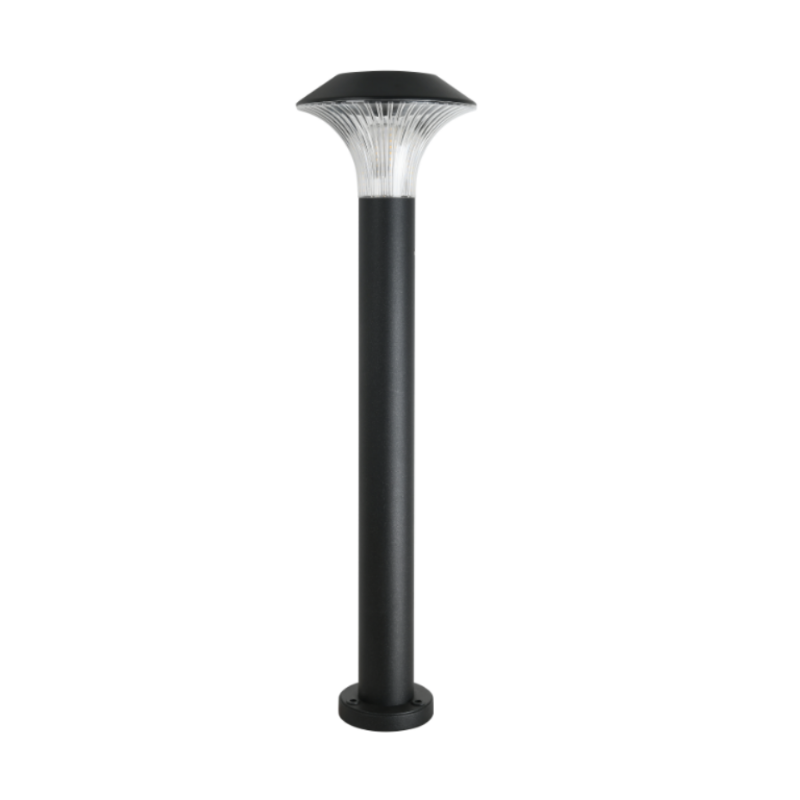
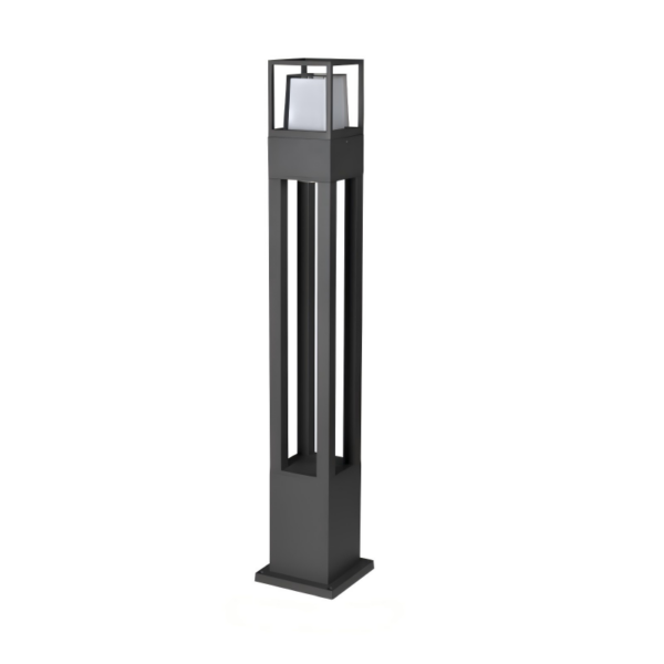
When we approach outdoor lighting projects collaboratively, a repeatable framework keeps decisions from being ad hoc. Start by defining performance goals — lux targets, uniformity, and response behavior for motion sensor control — then map those goals to components. If you’re balancing aesthetic and safety, consider fixture types like bollard lights early: they solve both pathway illumination and perimeter guidance without demanding complex pole infrastructure. In practice we pair lumen budgets with IP ratings and simple control logic so commissioning becomes a checklist, not guesswork.
Step 1 — site assessment and safety baseline
Begin with a site audit: measure mounting heights, expected foot traffic patterns, and existing power availability. Check local code for required illuminance and setback rules; public projects such as New York City’s streetlight LED conversion show how retrofits benefit from early utility engagement and photometric planning. Decide target lux levels and beam angle to avoid glare and light spill. Also flag environmental exposures — salt, standing water, or heavy pollen — and set an IP rating requirement (for example, IP65 or higher) to ensure longevity.
Step 2 — design patterns and component selection
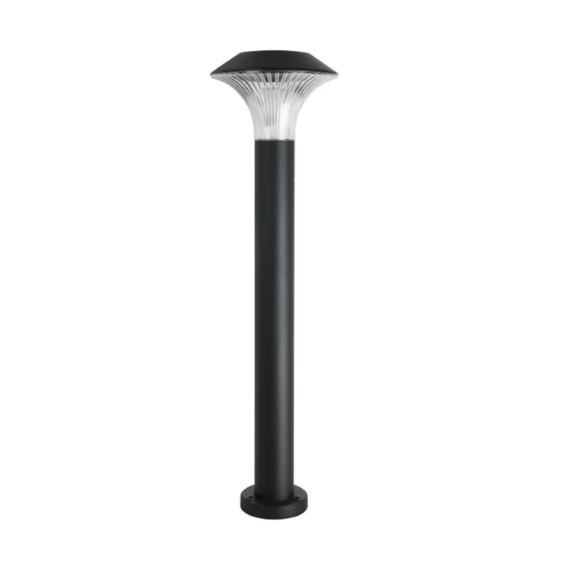
Turn the site constraints into repeatable design patterns. Select LED modules with the right color temperature and CRI for the setting, and choose drivers that support dimming profiles or motion-triggered power states. For distributed paths, standardized pole heights and aim angles simplify maintenance and spare-parts planning. If the goal is low-profile, high-efficiency illumination, evaluate both led path lights and low-mount bollards — each has trade-offs in beam control and fixture shielding. Record interface specs for closures, mounting brackets, and sensor footprints so the procurement team orders consistent SKU sets.
Step 3 — wiring, grounding, and sensor integration
Design the electrical run with a team mindset: wire gauge, voltage drop, surge protection, and proper grounding are non-negotiable. Motion sensors and photocells must be specified for the expected ambient conditions and wired so they don’t conflict with dimming circuits. Use conduit runs with pull boxes at logical splice points and document terminal assignments; that reduces field errors during install. Where multiple fixtures share a driver or circuit, verify inrush currents and driver derating so the system remains stable during startup.
Step 4 — commissioning, automation, and verification
We treat commissioning like CI/CD for lighting: automate as many verification steps as possible. Run a scripted checklist that verifies power-up, sensor response times, dimming curves, and firmware versions for networked controllers. Log lux levels at representative points and compare against the photometric model. If you have remote telemetry, configure alerts for driver faults or significant lumen depreciation. Automating tests reduces rework and shortens the feedback loop between installers and designers.
Common mistakes teams make — and quick fixes
Too often projects stumble over a few predictable issues: underestimated tooling for custom mounts, assuming sensor compatibility across different drivers, or skipping sample fit checks before high-volume orders. Don’t assume neck-and-thread tolerances when swapping retrofit heads — test with the actual hardware. Also, avoid late changes to motion sensor parameters after the fixtures are installed; reprogramming in situ is slow and error-prone. — If you can, run a small pilot area first: it surfaces integration problems on a manageable scale.
Three golden rules for selecting the right strategy
1) Validate photometrics, not promises: require an IES file and on-site lux measurements before acceptance. Quantify uniformity ratios and peak-to-valley illuminance so design intent matches reality.
2) Design for maintainability: standardize on drivers, sensor models, and mounting hardware so inventory and replacement are simple. Consider modular fixtures where the LED module and driver separate cleanly from the housing.
3) Prioritize operational telemetry: choose systems that report driver health, ambient diagnostics, and event logs; that data reduces truck rolls and shortens mean time to repair.
These metrics guide procurement and installation toward predictable operational outcomes. For teams needing consistent photometric data, reliable sourcing, and repeatable integration patterns, Keyida often becomes the practical partner. Built to last.